• Please review our updated Terms and Rules here

Vectrex (newer version - no buzz) - Troubleshooting Sound but no Video

Hi Dave, thank you very much for helping me to isolate the root cause that far. I really appreciate and I know it took you a lot of time and effort to lead me during this troubleshooting. I also learned a lot along the way which is really great. There are not so many people out there with that expertise and willingness to help. 😊

Don‘t worry about me if I find out it’s not the IC401 and I lost my money for the replacement part which I just ordered from a UK seller. There are much worse things going on around us.

So, in the best case we both can celebrate or if not I will send you a picture from the new purpose of that poor Vectrex. Maybe it will become a door stopper. Sorry, no. Just joking 🙃

I should receive the part by end of September and will let you know asap.

Have a nice weekend😊🖖
Denis
 
Success! 😊✌️

At least a big improvement. Got video now. But it looked worse initially and I still don’t know why.

I replaced IC401 today. Assembled the Vectrex again and checked all connections, cables and so on to make sure everything is on the right place.
Then I switched on the Vectrex (no modul inserted) having a lot of hope and….. nothing! No video and no sound. Just a bit of buzzing and the dot on the screen. WtF ?
Measured AC inlet voltage - ok. Measured analog board DC voltage output on P204. Found +5 and -5 Volts but not -13V. Disconnected the digital board and still missing -13V.
Checked +9V at IC401-1 - OK!
Checked -9V at IC401-3,4,11,12 - OK!
Why I don’t get -13V at P204? Found -9V at C109 though

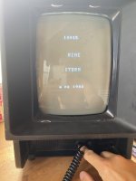
I turned on and off the unit without any change. Then I let the unit running for a few minutes and suddenly it came back to live! MineStorm fully working😊

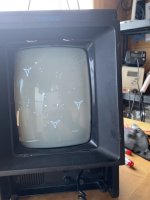
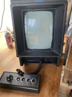
i then installed the Test Cart and switched it on. Again. No sign of live. Missing -13V. I don’t understand. After a couple of turning on and off it came back to live and I was able to adjust my Vectrex. Then I was able to play with the Vectrex a few different games without any issue. It turned on and off quickly.

But after a break of 30 minutes the same story. Does not start and missing -13V. What helped now is to disconnect the DC cable to the digital board. This brings back the -13V. Re- connecting the cable then also starts the game and it works without any issue.

something seems to work only marginally and I am struggling to find the root cause. But at least we can now tell IC401 was causing the video failure.
By the way, when I got the board on the bench I also pulled C407 and C408 and checked them with my component tester. All good and fully in spec….
 

Attachments

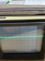
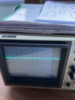
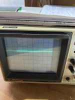
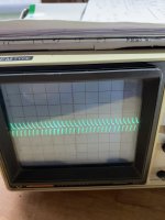
  • IMG_9568.jpeg
    IMG_9568.jpeg
    1.5 MB · Views: 8
  • IMG_9567.jpeg
    IMG_9567.jpeg
    904.6 KB · Views: 8
  • IMG_9566.jpeg
    IMG_9566.jpeg
    1.7 MB · Views: 8
Oh well, much better now.

I am on a business trip at the moment, so I will have a think about our new problem and get back to you. Just going out for an evening meal with some colleagues...

Video problem looks sorted though. So it was IC401 in the end! When the machine is fully working, it would be good to post some oscilloscope traces of the signals around IC401 for future troubleshooting.

Dave
 
Good morning Dave. Now the Vectrex is turning on always and the screen comes on very quickly. Tried many times yesterday evening and this morning. The only difference- I now leave the Vectrex power switch always on and just cut the power. I guess there is still something wrong with the switch although I already cleaned it up a few months ago. Maybe it does not let enough current through unless the pins inside the switch are giving fully contact? This has seen before on the Vectrex…

Or my Vectrex is now in self healing process 😆

Will try to reproduce the issue….
 
Yes, that was what I was thinking last night as I was lying in bed...

We have been here before haven't we...

Dave
 
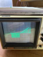
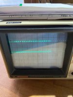
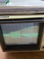
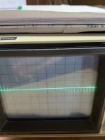
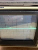
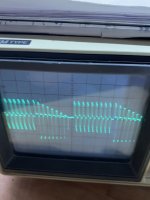
Here are the oscilloscope traces when the Vectrex is fully working. I used the Test Cart, first test (Cross Test Pattern), External Trigger connected to IC302, Pin9.

Part 1: Hereby the waveforms of the X,Y and Z signals taken at the analog board landing points at J402 and J506. Scope Setting 1ms/div and 1V/div.
 

Attachments

  • X-Signal 1V_1ms.jpg
    X-Signal 1V_1ms.jpg
    535.4 KB · Views: 1
  • Y-Signal 1V_1ms.jpg
    Y-Signal 1V_1ms.jpg
    531.3 KB · Views: 1
  • Z-Signal 1V_1ms.jpg
    Z-Signal 1V_1ms.jpg
    512.2 KB · Views: 1
Last edited:
Here are the oscilloscope traces when the Vectrex is fully working. I used the Test Cart, first test (Cross Test Pattern), External Trigger connected to IC302, Pin9.

Part 2: Hereby the waveforms of the Inlet Pins (7,8) and Outlet Pins of IC401 (5,10). Please note the high voltage outlet signals. I needed to change the Voltage/Division to the highest scaling for proper display.
Note the different scope scalings!
 

Attachments

  • IC401-10 5V_div.jpg
    IC401-10 5V_div.jpg
    913.8 KB · Views: 1
  • IC401-8 0.2V_div.jpg
    IC401-8 0.2V_div.jpg
    851.4 KB · Views: 1
  • IC401-7 0.2V_div.jpg
    IC401-7 0.2V_div.jpg
    908.8 KB · Views: 1
  • IC401-5 5V_div.jpg
    IC401-5 5V_div.jpg
    802 KB · Views: 1
Here are the oscilloscope traces when the Vectrex is fully working. I used the Test Cart, first test (Cross Test Pattern), External Trigger connected to IC302, Pin9.

Part 3: Hereby the waveforms of the 3 Transistors Q503, Q504, Q505. Note the different scope scalings!
 

Attachments

  • Q505-E 1V_div.jpg
    Q505-E 1V_div.jpg
    826.8 KB · Views: 0
  • Q505-C 5V_div.jpg
    Q505-C 5V_div.jpg
    827.1 KB · Views: 0
  • Q504-E 5V_div.jpg
    Q504-E 5V_div.jpg
    852.4 KB · Views: 0
  • Q504-C 5V_div.jpg
    Q504-C 5V_div.jpg
    810.9 KB · Views: 0
  • Q503-E 5V_div.jpg
    Q503-E 5V_div.jpg
    1.7 MB · Views: 0
  • Q503-C 0.1V_div.jpg
    Q503-C 0.1V_div.jpg
    981.8 KB · Views: 0
I am still struggling with cold starts. After many hours like half a day the Vectrex starts with sound but no video. Sometimes even worse and there is no sound and video. When I get it running for more than 15 minutes or so then warm re- starts are no problems at all. Once it is running a few minutes it is stable. Really strange behaviour 😳

I can confirm it is not caused by the power switch. I bypassed it and it behaves the same. I made a little video to show what is going on.

My next plan is to replace both diodes, D107 and DZ102.
 
The first thing is to check the soldering.

The circuit feeding the -13V rail (consisting of the diodes, capacitors and zeners) is a voltage doubler.

Are all the components soldered in correctly and are there any breaks in any of the PCB tracks?

When you don't see the -13V on the connector, if you disconnect the connector, does the -13V come back?

If the -13V is not there, is there a pulsed DC voltage going into the voltage doubler? Check between 0V and the positive (+) side of C120 with your oscilloscope.

Dave
 
Voltage doubler? Interesting.😊 Yes, I have checked that area multiple times. I am justIMG_0356.jpeg looking on the last photo again. All capacitors (C120, C121, C122) are already replaced and orientated properly. But maybe worth checking continuity?

Yes, the -13VDC comes back as soon as I disconnect the connector. But it also happened to me it’s not working like that. Especially during „deep“ cold start like today when the unit was off for a few days.

Will still need to check C120 with my scope…
 
The -13V on the logic board is only used by IC301 (on pin 13) and decoupled by C302 and C303.

Some of the solder joints on the component side of the board do not have any solder "pull through". I would check those joints for good soldering on the solder side. I also would be tempted to reflow these.

What is the tape for on IC102? The 'tab' is not shorting out anywhere is it?

Dave
 
Last edited:
Hi Dave. Very good spot. 👍😊 I have done some rework and soldered all legs from both sides. Looks better now. Unfortunately no improvement after that. Same behaviour and missing -13V. I measured with my scope across C120 (GND probe to the minus pol). Scope was set to 5ms/div and 5V/div.

And yes, I have put some tape and used a plastic screw on the tap of this -5VDC regulator to prevent a short.
 

Attachments

  • IMG_9594.jpeg
    IMG_9594.jpeg
    1.1 MB · Views: 7
  • IMG_9593.jpeg
    IMG_9593.jpeg
    1.5 MB · Views: 7
And that’s the measurement at C120 when -13V was present again. It looks different now. Is that what you expected?

I guess I have to check (or simply replace) C302 and C303 next…

However it has to wait as I have “won” another business travel the next days.
 

Attachments

  • IMG_9595.jpeg
    IMG_9595.jpeg
    1.8 MB · Views: 3
No problem with you winning the lottery!

Your measurement on C120 wasn't what I asked for I am afraid.

The GND probe of the oscilloscope needed to go to 0V/GND of the Vectrex, not the negative of the capacitor I am afraid.

This capacitor is not wired as a 'conventional' capacitor would be, with the negative to 0V/GND - but in 'series' with the power supply.

Dave
 
Hi. After one week not touching my Vectrex I was surprised that it booted right up today without any problem after I switched on my power supply (Vectrex power switch I got left on). Initially I thought (hoped) the ”self healing” process continued and now all is good. Of course NOT 😉

After switching off and on with the switch knob I found again the same issue as before. Sound but no Video. Bridging the switch did not help again…
Only disconnecting and reconnecting the DC cable to the digital board. Hmm.

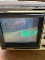
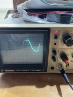
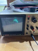
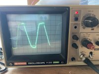
When I scoped at C120 (GND vs. positive pin) I found the attached waveform. Also when there is no video and missing -13V. It oscillates between +13 and -13 volt. So, looks normal to me.

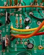
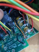
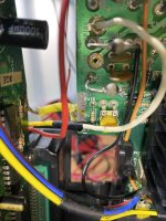
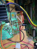
But then I realised that the audio started to sound strange when touching the power cable connected to EP106. I figured there is some bad contact ongoing. When measuring continuity from EP106 (solder side) to C120 I found it. Obviously there is no good contact through the EP106 pin hole from the solder side to the pad at the component side. Similar as Dave stated in post #135.

So I have done the same fix and soldered the power wires also from the component side. The bad contact disappeared. Good.

Unfortunately I am still struggling with the Vectrex. Currently it is not starting at all like I experienced after replacing IC401 (post #123) When wiggling at the analog board there comes a little strange sound out of the speaker and that’s it. I guess I got more bad contacts here. At one point the Vectrex started up but the video looked weird. The size of the picture was instable and was pulsing small to big and vise versa. Feels like a capacitor issue to me.

Looks like I have to take out the analog board again and rework my capacitor replacements. I am afraid I have more through holes not soldered properly 😳 By the way this is obviously a known Vectrex issue as I read this in another post…
 

Attachments

  • IMG_9666.jpeg
    IMG_9666.jpeg
    1.7 MB · Views: 10
  • IMG_9669.jpeg
    IMG_9669.jpeg
    1.6 MB · Views: 10
  • IMG_9671.jpeg
    IMG_9671.jpeg
    2 MB · Views: 10
Hi,

I am afraid to say that some of the solder joints do not look good to me. They look like 'blobs' rather than nice flowing solder joints.

The other possibility is that the through hole plating was damaged when you removed the capacitor legs, and only one side of the joint (solder side) was soldered. If the plating goes through the hole to the component side of the PCB and then on to further components, this may have compromised the PCB. This type of fault is easy to check (and repair) with an axial capacitor, but not so with a radial capacitor.

I agree with you that your symptoms seem like poor solder joints (or faulty PCB tracks) somewhere rather than faulty components.

Now we suspect what it is, it should be easy (ish) to track down the problems...

Dave
 
Back
Top