• Please review our updated Terms and Rules here

Vectrex Repair (another no buzz 3GE version)

Dave i have added another video named joystick movement.

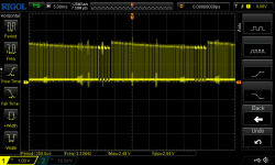
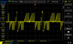
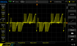
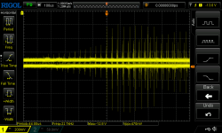
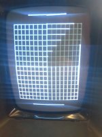
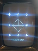
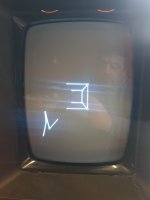
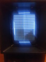
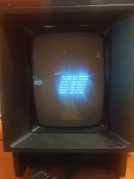
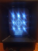
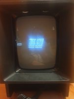
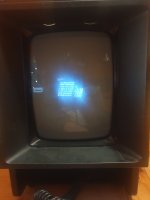
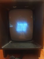
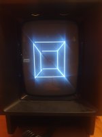
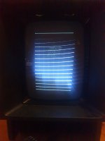
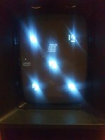
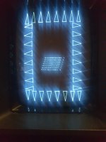
And here all screen of test cartridge.
 

Attachments

  • 20231203_223731.jpg
    20231203_223731.jpg
    1.2 MB · Views: 5
  • 20231203_223744.jpg
    20231203_223744.jpg
    557.7 KB · Views: 5
  • 20231203_223753.jpg
    20231203_223753.jpg
    841.2 KB · Views: 4
  • 20231203_223756.jpg
    20231203_223756.jpg
    637.3 KB · Views: 4
  • 20231203_223759.jpg
    20231203_223759.jpg
    538.4 KB · Views: 2
  • 20231203_223806.jpg
    20231203_223806.jpg
    573.3 KB · Views: 4
  • 20231203_223814.jpg
    20231203_223814.jpg
    498.2 KB · Views: 5
  • 20231203_223830.jpg
    20231203_223830.jpg
    896.7 KB · Views: 5
  • 20231203_223836.jpg
    20231203_223836.jpg
    1.3 MB · Views: 5
  • 20231203_223848.jpg
    20231203_223848.jpg
    1 MB · Views: 5
And, again measurement with a different time and voltage div
 

Attachments

  • Z axis wave 2.png
    Z axis wave 2.png
    48.8 KB · Views: 2
  • Y axis wave 2.png
    Y axis wave 2.png
    57.6 KB · Views: 2
  • X axis wave 2.png
    X axis wave 2.png
    55.8 KB · Views: 3
  • -13v ripple.png
    -13v ripple.png
    59.2 KB · Views: 3
  • 5 volt ripple.png
    5 volt ripple.png
    38.9 KB · Views: 3
  • -5 volt ripple.png
    42.6 KB · Views: 1
And just for info, during 3 hours continuosly of power on the system it going to almost perfect status and i have played with mine storm and scramble and the vector are almost very good. Then i have turned off system for about 15 min and i jave observed the grid of test cart, all vectors going very slowely to correct and precedent position.

i think so the problem is not on logic board, it seems a bad resistor or capacitor (not electrolityc because very all are new now, comprensive the little bipolar bottom of heatsink.

I don't know how or where to heat components to simulate this change, it's very inconvenient for a small space.

A question for last video with controller movements, it's normal when i move pads in a controller test scree i watch movement on both controller and only button is only to one?

Aaarggh....this vectrex have sucked my patients! I'm going to bad.
 
Last edited:
Another notice, when system is hot and working all XYZ signals are the same of photo posted previously, do not change anything, and i have watched signals of MIATA but all are little different !
 
Last edited:
I think we both need a break from this evil machine.

Let's have a week off shall we, and reconvene next week?

If the machine is temperature sensitive, it is unlikely to be a resistor (unless it is a power resistor) in which case it will be stressed, and therefore hot.

It could be a capacitor or an IC.

Do you have any 'proper' freezer spray? If not, I suggest you purchase a can. You then go around the ICs and transistors one at a time and freeze them when the machine is hot and observe the display. If it doesn't change, you tick that component off on the schematic. You need to be fairly 'directional' when using the spray. You do not want to cool down other competes at the same time, otherwise this will skew the results! I get some cardboard and make a little 'walled garden' for the component to keep the freezer spray confined to the component I am testing.

When you find an 'iffy' component - and the screen suddenly changes - let it warm up again and repeat the spray process. You will, hopefully, get the same results (the scientific methodology). If so, replace the faulty part.

Dave
 
Yes i take pause from this devil!

But, the only two chips not interchanged with new (at the moment it have all original chips) are the sound chip and the NE555 and 7805 regulator (LM340 in my case). All electrolytic capacitor replaced now. The four diode on the AC input are new. The 7905 are new. Two 2n3905 on logic board are new. Only zeners, little transistors on analog and not polarized capacitor are old.
 
If oscillator 555 and circuit to drive it non working good, or......high voltage is not enough at cold, if possible a similar fault cause distortion of image?
 

Attachments

  • 1701900370847.png
    1701900370847.png
    234.6 KB · Views: 3
Nope, I have already stated this.

If the 555 circuit or the high voltage circuit is faulty this should only affect the CRT brightness and/or focus - not the vectors.

The deflection amplifier (IC401) is powered from the +/-9V unregulated supplies. You have checked these haven't you?

EDIT: Hang on, -30V sneaks into the blanking circuit. You have checked the -30V rail as well haven't you?

Dave
 
Last edited:
I remember doing it but probably with the hot system, I would say I can do it like this, I connect two multimeters, one for -30v and one for +-9v and I try to turn it on to see if I have correct or variable voltages in the time it takes to heat up . At this point I exclude the 555 and it's good, IC401 (LM379) is new, I always changed it to understand if it was the problem but nothing has changed. I check these voltages this evening by soldering the wires and connecting the multimeters in the right places, I also thought about 170v, but I remember seeing them at around 169v.

I have to check in this yellow point the voltage right?
And i have to check also the red marked component?

1701944511619.png
 
Yes,

Put the negative side of your multimeter on the 0V/GND point and measure the three yellow points you have identified on the schematic with the positive side of your multimeter. You can also measure the +50V and +170V at the same time if you like. It will only take a few more minutes - since you are there.

Dave
 
The -30V rail is an output.

D506 provides half-wave rectification and C508 is the smoothing capacitor.

Dave
 
Today I turned the system on cold after 4 days of being stopped, the video image was not completely distorted like the photo from a few days ago when you wrote disaster! I only had to adjust r333 and r335 a bit to get it almost perfect with the system on for less than 2 minutes! However, I measured the voltages and:

9v rail is 12.3v
-9v rail is -12.8v
-30 rail is -35.4v
170v rail is 164.8v

and they don't change as long as I keep it on!

This system is really making me lose patience, I haven't touched anything since the last tests.

I notice that some vectors are not precise in some games such as pole position, when the curve is to the right the left edge of the track is bent too much towards the center, or in mine storm the shuttle when it descends has small vectors in the base that are out of position.

The problem remains with the diamonds screen which only has the large one in the center, but the grid is ok!

It have the incredible!

See the third photo with square of distortion2 test with left vector totally out of position. Only this problem today it have!
 

Attachments

  • 20231208_154409.jpg
    20231208_154409.jpg
    894.5 KB · Views: 2
  • 20231208_154241.jpg
    20231208_154241.jpg
    891 KB · Views: 2
  • 20231208_154221.jpg
    20231208_154221.jpg
    597 KB · Views: 2
  • 20231208_155140.mp4
    4.7 MB
Last edited:
The vector out of position in photo 154221 if I just bring my finger very close to one of the 34001 it goes into its correct position and the squares can all be seen ok, as soon as I move away it goes back to like the previous photo.
 
The problem in pole position on the track border is for the same problem of square photo, if i put finger on 34001 the track is correctly displayed. Same for mine storm, the ship is correct if i put finger aprox the 34001. I have turned of system for 30 minutes than again on and it stay little distorted bit for about 30 seconds then it's ok. Damn!
 
Last edited:
Ok, so the DC rails look OK.

Don't get too exasperated. These things never fix themselves!

Question: Is your ROM soldered into the board or is it in a socket?

Dave
 
it's soldered and the two logic chips 7432 and 7402 i remember too. But i don't know why today i don't have full distortion! I have played now for one our with 4 different game and it's perfect, only little vectors not centered properly for the beam square problem but all playable!

I have urted both board with screw driver for check if i have a false contact but nothing change, today it's working.
 
Last edited:
As I said, things don't fix themselves...

So it is likely that you have a bad contact somewhere. But these are evil to find. You need to check every pin of every component to make sure it is correctly connected on the solder side and the component side of the PCB.

The trouble is, if it is 'fixed', it will be difficult to find until it goes wrong again.

It could still be a temperature related issue, but a bad contact can also manifest itself asctemperature related.

Dave
 
Back
Top