• Please review our updated Terms and Rules here

Vectrex Repair (another no buzz 3GE version)

Hi,

Sorry, I got distracted (again) this afternoon.

I promise I will have a look at your posts tomorrow morning.

Dave
 
Ok no problem, in the time I have buyed another vectrex with similar initial problem of my, then when i repair both I sell one. :D
 
Hi Dave, this evening I spent a lot of time on the vectrex, I once again cleaned the area of the operational amplifiers where there was a bit of dirt, thinking that it could generate high resistances between the pins of the components, then I rechecked the connections between them again, I also desoldered the 3 potentiometers to check their status.
There are 2 10k potentiometers for the x y adjustments and one 2k for the dac offset. one of the two gave me a value of 11.2k unlike the other with 10.2k, I don't think it's a problem. I then tested all the chips again with old and new, I found no differences. I studied the differences between the scheme and the 3g and nobuz board, basically the 2 34001s manage the outputs of the x and y axes while the 34004 manages the z axis and something related to the dac offset. I again set the offset at 0 volts using first the oscilloscope and finally the multimeter, it is perfectly at 0v when the test image disappears. However, I noticed something very strange, before I attempted to change the integration capacitors, which I then made a mistake and was forced to reassemble the old ones, the two 10k potentiometers allowed me to adjust the image correctly, this always in the system hot , and the position of the wheel of both was almost the same, while now one of the two is at full scale and does not allow me to adjust as well as before. Seeing that everything works through the 34001 and some resistors and with the two voltages +5ana and -5ana, I checked that everything was connected according to the diagram. as connections, although different on this board, correspond to what the diagram states that they should do but I noticed that the values written in the diagram do not appear to me, that is, in the two potentiometers the diagram says that the two side pins 1 and 3 should be connected respectively to -5ana and +5ana, but with the multimeter I saw that for R335 it corresponds to what the diagram says and therefore corresponds to pins 7 and 14 of the 4066. For the other, however, this is not the case despite the diagram indicating the same thing. I then turned it on to check the voltages with the multimeter and I saw that instead on both potentiometers I have a negative voltage of -4.98v on external pins 1 and 3, I shouldn't have -5v and +5v on them as the diagram says ?
Then I checked the resistors in the circuit in this area and they are all ok.
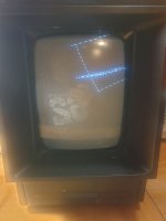
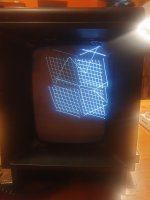
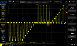
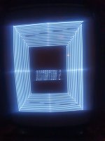
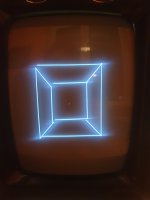
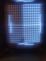
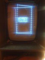
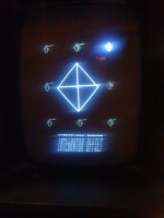
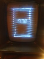
Then I connected the test cartridge again choosing test distortion 2, the one with the two squares one inside the other and I saw that I always have the left side with two vectors completely out on their own, I brought my finger closer between 34004 and 34001 of the y axis and with my finger the two vectors tend to return to their correct place, if I move my finger away they go back out of the pattern! At this point I think they could really be the integration capacitors since I changed everything in the area except them, even though they would seem good. In all this time of testing the system has warmed up very well but despite everything the adjustments cannot be made properly and in the games you can see graphic errors in the positioning of the vectors or the writings upside down, or compressed or even too enlarged.
I put in the scramble game, which seems to be pretty ok except for the fact that in the second level the upper rocks move along with the movement of the controller!

Given this, I'm starting to think that it could be a defect in the audio chip or the RAM!

I don't know where to look anymore, I'm giving up, I probably won't be able to understand the problem and will have to abandon it, the only problems I have are the 4066 which I will try to test on a Commodore64 tomorrow.

I'm really tired of taking everything apart every time and then not solving it.

At the moment there are all new components, both on analog and logical boards, except the integration capacitors, or I should remove the new sockets that I put in and check again if there is any problem underneath them.

I don't know
 
Good morning demonlg

Don't give up! I know how frustrated you are now but once again - make a break and step back. Consider how much solder work you have done to this board especially when installing all of these sockets. It may happened to you that you have an intermittent contact issue. You are telling that the behaviour of the Vectrex changes when touching the board. This really sounds like a contact issue to me. Happened to me all that often. Especially on these kind of old, low quality PCBs.

I suggest to look with a magnifier glass on the areas you were soldering. Especially around the chips you mentioned above. If you can’t find anything you may just don’t see the bad contact (or short). Use your multimeter in continuous mode (beep mode) and ping from the chip legs to the next contacts. Make sure the legs are not shorted to each other.

I got an odd issue 2 years ago when trying to repair a Sinclair Spectrum. Could not found the issue after replacing all RAMs. But with the multimeter I found a short between 2 legs caused by a tiny, tiny copper wire which was a left over from working with solder wick!

Good luck!
 
OK, I am yours for the remainder of the afternoon!

This is why I find the approach of replacing everything in sight and not getting anywhere demoralising - hence the reason I generally prefer to use as many 'non intrusive' test techniques as possible to start with and only replace components when we either (a) have a potential good reason to or (b) we can't get any further with testing until we eliminate a component or two from the equation.

If devices are in sockets, I see no reason not to do a 'blanket swap' to see what happens. In this case, however, I generally mark the original components with a coloured dot of paint to identify the originals and put as much back as possible when I have finished.

75% of repairs are relatively simple and an be accomplished by a few device replacements. This can 'suck' people into a situation where they replace parts and the fault doesn't change. So they replace some more parts and the fault doesn't change. So they... By the time they have finished they have either a new machine that works or a machine with new parts that doesn't work! I suspect you have the latter now?

The other problem is that by changing the parts you may have changed the presentation of the fault. This either indicates that (a) you have fixed something when you have swapped parts - but we don't know why; (b) you have inadvertently introduced a faulty component thereby introducing a new fault that we didn't have before; (c) introduction of replacement parts necessitate adjustment of the potentiometers - but we can't successfully adjust the potentiometers to achieve the desired effect because of a further fault.

If you haven't replaced the integrator capacitors - and these are the only thing on the analogue board that you haven't already replaced - I would suggest going ahead and replacing them. The integrator capacitors are quite important - and if one (or both) are not good we will be kicking ourselves at this stage.

QUESTION: Am I correct in assuming now that the machine does NOT give us correct vectors when it is warm/hot any more?

The 2114 RAM devices are unlikely to be faulty. You need both devices to be working to give you the requisite 1KB RAM. Normally, you will get a stuck data bit (either stuck at '0' or '1') or an addressing fault. Both of these scenarios are likely to result in the game crashing. The stack (and other key variables) are stored in the RAM and this will be detrimental to the operation of the machine in this case. When a Commodore PET has faulty page 0 RAM - that is 'end of go' for the machine operating. This is why my PETTESTER doesn't use any RAM when it attempts to check that this RAM is actually working.

Same with the audio device (AY3-8912). This device produces 3 channels of audio sound, but it is also responsible for the controller buttons.

QUESTION: Do the controller buttons work or not with the test cartridge?

The 4052B analogue multiplexer also controls one channel of audio output. This is the same device that is responsible for generating vectors.

After replacing the integrator capacitors, I would concentrate on the effect your finger has on the vectors... It sounds daft (!) but it gives us something to work with.

Install the test cartridge and get the screen displayed that we can use for the test. Ideally, this will be the crosshatch screen if possible.

Measure the X, Y and Z signal without your finger near the devices. Acquire photographs of the traces. Try and get at least one full cycle of the X and Y traces - keep the oscilloscope with the same timebase and Y settings once you are ready.

Then take the same set of traces with your finger near the device(s) that makes things better.

QUESTION: What has changed between the oscilloscope traces?

If we can find something that changes, we can then 'home in' on that part of the circuit to see exactly where the change occurs.

Dave
 
Last edited:
Ok, Dave and miata, tomorrow i try to replace integrator.

The controller is working with test carttridge all button and all direction, but when i move on screen move vectors on correct controller port and little on other controlelr port too!

At the moment all component are the original, only the LM379 on bottom of heatsync and 6522 are new, and electrolytic cap.
I make a photo of system at cold and abount 30 minute tomorrow. the problem is the same of prior but now i have the issue on regulation potentiometer, seems not work correctly or seems not sufficient for alling all vector, but the very strange problem is when i put my finger on 34004 or on one of 34001 (only one used for Y axis not on other one used for X axis).

Miata says to check short on sockets, yes i have user multimeter pins to pins one to one but i dont't have found any short, only have short where pins is in short corrispectively on schematics.
I have tested last month the integrator with my multi component tester, the value is not very perfect to value writed on component, little low of value respect a correct value.

I hope is not a deflection circuit fault or tube fault or eat fault.

I try to make photo of X and Y with and without finger on top of op amp.

I was thinking of redesigning the circuit of the 3GE logic board model in question, it is very similar to what I posted but the operational amplifiers and the value of the integration capacitors change. The analogue card seems the same as others, except for a few fewer components near the 555. We will also see what it has inside the other Vectrex that I bought, this one also has a defect on the vectors, it seems that you can see something in the upper part of the screen only, but in my opinion this one really has exhausted capacitors, while mine actually didn't have them. I was stupid to change the capacitors before anything and before I had solved the 7905 regulator problem. In the end I realized that I had not changed two 1000uf 35v capacitors in the deflection circuit immediately after the I actually checked every track, every pin, even on the analog board several times, the only thing I found was that tin bubble that shorted pin 4 and pin 5 of controller port 0, nothing else, unless that there really isn't anything microscopic under the sockets. What I still don't understand is that strange impulse on the Z axis, I can't really understand what it's due to, I've checked everything but nothing can be done! I'm only sorry that I can't show you the measurements live, unless there is the possibility of making a live call while I carry out these measurements.
 
>>> I hope is not a deflection circuit fault or tube fault or eat fault.

Highly unlikely. A tube fault would present itself as low or high brightness. An 'eat' fault (heater?) is also unlikely. A heater normally goes open circuit (no video at all) or poor heating, in which case it is the brightness that suffers again.

It is also unlikely to be a deflection fault, but we can't totally rule that out. It is unlikely that it is a deflection fault if putting your finger near the OPAMPS can affect the display!

>>> but now i have the issue on regulation potentiometer.

I am not sure what you mean here. Which potentiometer are you talking about?

Your problem is also unlikely to be a short circuit (in my opinion). More likely it is an open circuit, or a poor connection between components, PCB tracks and and pins.

However, this may not be the case with the Z axis. You may, therefore, have two (2) separate faults.

We have to pick one cause and effect (your finger!) and work through this problem until we get stuck or fix the problem... We then move on to the Z axis issue (if the two issues turned out not to be connected with each other).

I would resist the temptation to change ANY component values without understanding exactly what you are doing and why. It is highly likely that these are a factory modification, and you really need to understand the version control information from the factory.

Remember what happened when you bought the wrong capacitor kit!

Dave
 
Last edited:
Ok, i have decided! Today i replace again all socket, at the moment i have replaced from init of this discussiin the audio chip socket, 6522 socket, cpu socket and all op amp and dac socket.

I try to remove all again, try to clean the zone from dirt and any extra solder iron and then i resolder new socket, i have all new socket and a strip of gold and conic pins, probably it are good to check if the solder iron pass from bottom layer and top layer correctly.

Then i replace integrator caps.
 
I (personally) wouldn't replace the sockets yet again...

The simplest and easiest solution is to replace the integrator capacitors and then use your brain and test equipment to find the problem - especially as it seems isolated to the one vector channel and (possibly) the Z axis.

Replacing stuff that already works is (in my opinion) a waste of time and will most likely introduce a new fault where there wasn't one in the first place.

You have one (possibly two) faulty connections or faulty components.

A couple of evenings with a pen, the schematics and some test equipment and a glass or two of wine and you should have this sorted.

If not, it is unlikely to be an IC socket or soldering issue and you would have wasted your time by replacing the IC sockets in this case anyhow.

However, if you feel this is your only option - and it is your machine after all - then I can't stop you can I...

Dave
 
Ok, i change now only integrator, now i have the correct value new wima.

I will make a video off issue when i use my finger on op.
 
Hi dave, i don't have to upload videos but this is a link on my gdrive space with video uploaded

The correct sequence to watch are:
094621
094729
094955
095218

Now i try to replace integrator caps.


If you have problem to acces on my drive send me a message.
 
I have changed integrator caps and only socket of both 34001 and cleaned with isopropylic on bottom of this socket and bottom of xyz connector and around integrator caps and checked all connections from it and the both 34001 and the 34004 chips.

I have checked all resistors in this zone from xyz connector and rest of circuit, all are good and with correct value.

At the moment at first cold power on it seems little better from the video, any text of the game or test cart are just fine readable, but i don't sure if it is for caps replacement or because i have turned on system for the video in the last post, about 1 hour and 30 minute ago.....

Probably i have to regulate again dac offset and other, but the integrator test screen is very poor, i post photo in the next post.

Scramble game have a earth vector discontinued, the ship are distorted and not right designed..

I try to regulate all again.
 
Last edited:
Dave, according to this schematics (not 3GE but similar) it's correct measuring DAC OFFSET on the yellowed point?
pin 13 of 4052 or pin 8 of 4066, because i don't have LF353 but i have the 34004 and i don't know what is my pin 1 output on my chip corresponding to this schematics.

Or the measurement is to take from the IOUT wire?

Emanuel


1701607790206.png
 
Based to this good tutorial i have to test DAC OFFSET on pin 1 of LF353 IC304, this pins going to pin 13 of 4052, in my case i have to measure it to this pin 13 of 4052, probably it correspondig to a pin on a 34004 but i have to check.

But, when the screen says text i have a wave signal on scope, then when screen is black (correct moment to adj R302) i don't have a very pefect solid line on scope settet to 100mv/div and 10us/div, it is with ripple, low but present, is not the same of the photo below.


1701608850325.png
 
Don't measure on IOUT - that is a CURRENT and not a VOLTAGE.

Measure on the 4052 pin 13 as you have stated.

When you say 'ripple', do you know what frequency it is and what the pk-pk voltage amplitude is please. This will narrow it down to what is causing it.

My guess is that you have some 'ripple' (let's use the same word until we know otherwise) on the voltage rails.

Can you just double-check (with your oscilloscope) on the +5V ANA, -5V ANA and -13V voltage rails as to what the voltage level is and the ripple/noise. Use DC coupling for the DC measurement and AC coupling for the ripple and noise measurements. In terms of the ripple, sweep the oscilloscope timebase until you observe the frequency at which the highest ripple/noise occurs. Ripple should occur at either the frequency of the mains supply in your country - or twice that. Noise occurs at much higher frequencies than the mains frequency.

Your videos are 'interesting'... It appears to be both X and Y that are affected though - not just one axis.

Dave
 
Ok dave, i try now to regulate dac offset and i send you image of scope on 5v ana -5v ana and -13v and same on pin 13 of 4052. Give me time for this test.

For now i attached photo after 2 hour of power off, i jave turnee off it at 15:00 with boot screen not perfect but like to...and now it is again out of all!
 

Attachments

  • 20231203_171024.jpg
    20231203_171024.jpg
    820 KB · Views: 5
  • 20231203_171908.jpg
    20231203_171908.jpg
    1,006 KB · Views: 4
Last edited:
Ok Dave, now i have completed all regulations, in this time the machine stay turned on of about 1 hour and 45 minutes, i have perfectly setted DAC offset to 0 volt, first with scope and then with multimeter, now when screen is black i have 0.00v.

The system is now very hot about this time and now the grid with all regulations setted is very pretty and ok.
Attached all measurement with system hot, and any photo of boot screen before and after settings. The Wave of Y axis change in time when i put the
probe on the wire, this attached seems wrong but if i remove end reput probe again it's correct.

First boot screen photo is perfect? I don't know, the VECTREX text seems to be enlarged vertically, second photo of boot screen is after about 10-15 minutes of system off without change anything on the settings.

The diamond screen is centered but little diamond on top or bottom have a vector out of sense!
Then all other screens of test cart, watch the Deflection Protect squares, is little imperfect about this time system on.

Now i upload Photo and sing what is at hot system and what after 10-15 minute powered off.

The three photos of the screen on this post are with system hot and all settings.
 

Attachments

  • Z axis wave.png
    Z axis wave.png
    58.9 KB · Views: 3
  • Y axis wave.png
    Y axis wave.png
    53.9 KB · Views: 2
  • X axis wave.png
    X axis wave.png
    54.2 KB · Views: 2
  • ripple on 5vANA.png
    ripple on 5vANA.png
    49.6 KB · Views: 2
  • -5vANA-rail.png
    -5vANA-rail.png
    31.5 KB · Views: 3
  • 5vANA-rail.png
    5vANA-rail.png
    30.8 KB · Views: 4
  • ripple on -5vANA.png
    40.1 KB · Views: 0
  • 20231203_181019.jpg
    20231203_181019.jpg
    876.2 KB · Views: 3
  • 20231203_181051.jpg
    20231203_181051.jpg
    820.1 KB · Views: 3
  • 20231203_181111.jpg
    20231203_181111.jpg
    726.2 KB · Views: 2
Last edited:
Other photos

184331, 184305 and 184222 is about 10-15 min of system off and then again on, the 180915 and 182232 is with system hot with other photos in last post.

I don't know how to explain to you but I'll try, after having adjusted the two potentiometers R333 and R335 with the grid screen you see in the photo and which seems perfect, I noticed that by turning them off and on again after 10-15 minutes they lose the previous setting, then waiting for everything to warm up I notice that in any case I have to touch up these two potentiometers but they reach the end of their travel and I can't adjust them further, it's as if some value continuously changes at every switch on, I was even thinking that it could be the two 2n3905 transistors.

While for those carriers outside the diamonds I'm afraid it may depend on the 6522 or RAM or audio chip.

Everything you see now happens with both the original chips and the new ones, except the 6522 which remains new because the original is broken and creates the white dot in the center of the screen.
 

Attachments

  • 20231203_184331.jpg
    20231203_184331.jpg
    969 KB · Views: 2
  • 20231203_184305.jpg
    20231203_184305.jpg
    1,022.5 KB · Views: 2
  • 20231203_184222.jpg
    20231203_184222.jpg
    1,018.1 KB · Views: 3
  • 20231203_180915.jpg
    20231203_180915.jpg
    743.8 KB · Views: 3
  • 20231203_182232.jpg
    20231203_182232.jpg
    1.1 MB · Views: 3
Last edited:
P.S.

Unfortunately I lost the photo with the hot system grid screen, but the lines were really almost all perfectly aligned, even the four lateral edges.
 
Back
Top