• Please review our updated Terms and Rules here

Vectrex Repair (another no buzz 3GE version)

So, if the 4066 is plugged in, the Z axis strange waveform is not present at either of these points. What about the "right hand side" of the diode?

We have to get the strange reading again, because this is the same point (effectively) as you measured before when the reading was strange.

Dave
 
At this point i have same signal of z axis wire connector, the video on other post, with or without connector inserted on logic board.
 

Attachments

  • 20231115_110017.mp4
    3.8 MB
That is interesting.

So the 'rogue' signal is either related to the /BLANK signal or cross-talk with the PCB track between D302, R315 and the connector.

The action of the operational amplifier and the diode is to 'drag' the signal down. So, as it is the positive side of the Z signal that is a problem, it is unlikely to be the operational amplifier (assuming the diode is OK of course).

Just one question, you are using the same oscilloscope Y and timebase settings for the traces in posts #124 and #117?

If not, we are not comparing apples with apples...

Dave
 
:) Not, post 124 it is with 1ms/div and 10v/div, in post 117 it is 10ms/div and 5v/div.....and i don't remember if probe is setted in both case to x1 or x10...Today i will check again this signals with same settings.
 
Yes, if we are comparing signals the measuring instrument needs to be setup the same - otherwise we are potentially looking at different artefacts of the signal.

Dave
 
Hi, I haven't disappeared, I have very heavy work commitments these days and I'm working from 8 in the morning until 2am the next day, as soon as I'm free I'll do the checks again, even if I'm losing hope.
 
No problem.

I sometimes have the same issues with work.

When you are ready...

Also, having a break now and then can sometimes help!

Dave
 
Hi Dave,

i have found time to retesting output of Z axis on my vectrex, i hope my diagnose is clare for you.

I have measured signal on D302 1n4148 connected to pins 6 and 7 of the MC34004, then this two pins 6 and 7 are connected both at the positive of D302 and the negative of this diode are connected to the Z axis wire connector.

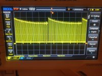
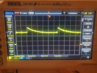
Now, i have setted scope with 5ms/div and 5v/div and the signal on pins 6 , 7 and positive of D302 are in the photo 002249, the signal on negative and Z axis wire connector are the photo 231117, same of previous post and WITH 4066 inserted in socket.

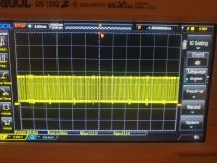
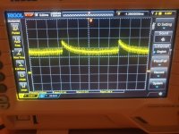
Then i have measured same pins WITHOUT 4066 inserted in, and signal is respective photo 232911 for pin 6 and 7 and positive, and photo 231552 are signal on negative and Z axis wire connector.


The result is, a Z axis is correct from.manual only when i remove 4066 from socket but is wrong and with strange peak if i insert it!

I have exchanged 8 different 4066 but i have same signals with all.

I don't know from the discendent ramp of photo 231117 is starting and because is present with 4066 connected!

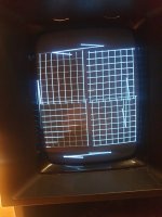
The photo 003238 rapresent the grid at with cold system and with 4066 inserted, if i remove 4066 i don't have vectors on screen.
 

Attachments

  • 20231126_231117.jpg
    20231126_231117.jpg
    3.1 MB · Views: 3
  • 20231126_231552.jpg
    20231126_231552.jpg
    2.9 MB · Views: 3
  • 20231126_232911.jpg
    20231126_232911.jpg
    2.4 MB · Views: 3
  • 20231127_002249.jpg
    20231127_002249.jpg
    2.6 MB · Views: 3
  • 20231127_003238.jpg
    20231127_003238.jpg
    1.1 MB · Views: 3
Last edited:
Give me until tomorrow - we are currently installing 86" monitors in our Church!

If you think it is a diode fault, a simple check with the power of and your multimeter set to read resistance should tell you. A diode will conduct one way and not the other (low resistance one way and high resistance the other).

However, this does not address the "cross-talk" between the 4066 and the Z-axis signal...

Dave
 
We are replacing our projectors and screens with modern 86" 4K monitors...

A better "congregation experience"...

Dave
 
Give me until tomorrow - we are currently installing 86" monitors in our Church!

If you think it is a diode fault, a simple check with the power of and your multimeter set to read resistance should tell you. A diode will conduct one way and not the other (low resistance one way and high resistance the other).

However, this does not address the "cross-talk" between the 4066 and the Z-axis signal...

Dave

The diode seems to be good if i test it with multimeter but with diode soldered on board, i have to desolder one point and test it again.

So, do you see Z cross-talk on 4066?
I can check if when desoldering the 4066 and soldering the new socket I made some mistakes in the soldering, but at least checking with the multimeter I think not.
 
Whether the 4066 is inserted or not should NOT affect the Z-AXIS signal.

The only way(s) I can see this happen is:

1. There is a solder splash or conductive path somewhere.

2. There is some effect occurring on the power rails.

3. The OPAMP used in the Z-AXIS circuit is common with something else that is faulty. On the schematic I have this would be IC303. Your PCB may be different to my schematic.

Dave
 
Hi dave, on my circuit the ic303 is a MC34004, in schematics it is LF347, this is a dual op amp, bit ot is good because i have replaced with new one and the problen persists.

Tomorrow i try to check solder points bottom of 4066 and 34004 and in the zone between both chips.

A questions, the z axis signal in photo without 4066 is correct?

If possible a fault solder point bottom of sockets in the top layer?
 
Hi dave, i have just now checked the ciruitry from z axis connector to thr op amp, and i don't have found any fault solder point or junction from z axis wires and other pins from 4066 or 34004!

I have noted the pin 19 of 6522 (BLANK) start from 6522 then going into a 2.2k resistor and then the resistor is connected to negative of D302 (z axis connector wire). seems to be ok from schematic.

Then i have found two pins of controller port 1 in short for little ball of solder iron, pins are pin 4 and 5 of right connector j203, now i jave resolved this.

Finally, i have a little difference on my logic board in the zone of 0volt trimmer, schematics says R303 connected from one pin of trimmer and pin 13 of cd4052, but on my board i don't have a resistor but a diode DZ303, connected in parallel of external pins of 0v trimmer, this diode signs in both sides with multimeter probably because i measure the resistance of the trimmer. Now i desolder it and test out of board.
 
Last edited:
Back
Top