• Please review our updated Terms and Rules here

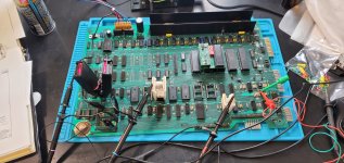
Starting my first Pet, a 4032 in desperate need of some love

Thanks Dave - I haven't really had cause to read it because I don't actually own a PET to put it in but the executable has been extremely useful several times over for remote troubleshooting other people's poorly PETs.

That's rather a lot of pulses to try to catch in the width of one screen and they will therefore be very narrow when captured that way. After we've counted how many _CS pulses Mike has captured, we may have to be content with only having the first five or so on screen so we can see what is happening to D0 (and ultimately the other data lines) during those pulses.
 
OK Question on the Reset button. Put it across the 1uf Tant on Pin 7 of the 555? It is not causing a reset.

Edit: I have to go to a recital for my Nephew so I will do more reading on the scope trigger and get back to it in the morning. On power up it seems to just trigger on some noise ringing on the /CS line and I did not find in the poorly translated manual how to multi-Trigger. Bedtime reading ahead!
 

Attachments

  • 20230320_161840.jpg
    20230320_161840.jpg
    2.4 MB · Views: 6
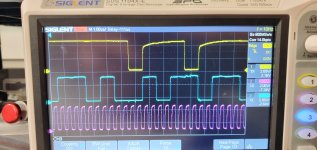
A little last second progress as I head out the door. Now I need to figure out how to capture longer or additional pulses.

It's coming back, albeit a bit slowly.
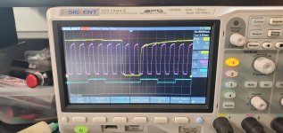
20230320_164634.jpg

All are at 1v per div. Yellow is /CS Pink is CLK and Blue is D0. The clamps may be making bad contact on D0 so I will double check in the AM.
 
The reset button should be from the 555 timer pin 2 to 0V/GND (across the 0.1 uF capacitor).

Dafe
That would explain why it's not working. I'll fix just thing in the AM. Right now I'm headed to listen to a couple hours of middle school band so i can hear my nephew for a couple minutes 🤪
 
Huh, wrong capacitor, sorry. This is why Dave isn't allowed to leave.

In the screen shot, the height of D0 (blue) obviously looks wrong. Is the slide switch on the probe you are using for that channel set to 'x10' by any chance?
 
Huh, wrong capacitor, sorry. This is why Dave isn't allowed to leave.

In the screen shot, the height of D0 (blue) obviously looks wrong. Is the slide switch on the probe you are using for that channel set to 'x10' by any chance?
Omg that's a brand new probe and i forgot to check when i opened it. . Here's hoping I'm smacking my forehead in the morning!
 
That looks like quite a decent scope - it might even have a pulse-count feature on it somewhere.

If not, in that screen shot you have just one CRTC _CS pulse, so now you need to try to adjust the horizontal time sweep so that you capture all of the initial burst of CRTC _CS pulses so you can count how many there are.

You don't really need to include the clock in the capture, that last shot does nicely illustrate the timing relationship between the _CS pulses and the clock but when you have the timebase slowed down to capture all of the _CS pulses the clock cycles (purple) will be very closely packed together. Just the post-reset CRTC _CS pulses will do initially, try to catch all of them so you can count how many there are, and then have a look at several _CS pulses (maybe five across the screen) with D0 captured at the same time so we can see if D0 assumes sane / valid states inside the duration of each _CS pulse.
 
Another morning, another cup of joe!

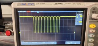
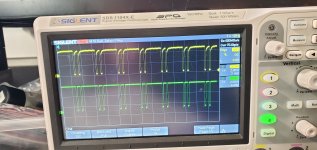
The D0 probe was indeed set to 10x. I hid the clock and dialed up the timebase and the result was that it is showing 18 pairs of /CS pulses. I also hooked up the reset to the other cap I had replaced and am using that instead of power cycling.

20230321_081519.jpg20230321_081530.jpg
1V/Div 50 uS


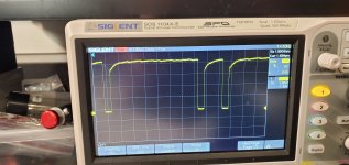
I then took a close up of one pulse pair with all lines

20230321_082521.jpg
2v/Div 1 uS

Mike
 
Excellent work.

So, 18 pairs of /CS pulses indicates that my PETTESTER code is attempting to initialise the CRTC.

Two possibilities:

1. The data bus is corrupt (on a write) so what the CPU is writing is not what the CRTC is storing.
2. The CRTC is dead.
3. Some other control line to the CRTC is broken. Don't forget to check the buffered R/W line out (BR/W)... I have got caught by this floosy before!

Dave
 
Yes, nicely done. It's very helpful to be able to show that the CPU is virtually 100% likely to be executing Dave's test code, there's really no other way you could get that nice line up of 18 pairs of CRTC _CS pulses, the exact number expected.

If you have the patience to do so, do similar captures with CRTC _CS - ideally at least four of those on-screen, and the CRTC R/_W pin, and each data line in turn.

If you can do that in a meticulous way we will be able to 'read' the first four bytes which are transacted between the CPU and the CRTC but for that to work the CRTC _CS pulses captured would always have to be the first four. Of course this would be much easier with a logic analyser which would capture whole bytes at once.

This may be an increasingly academic exercise if you already have a replacement CRTC on the way because it will be simpler just to put that in and see if it works, but it illustrates the sort of methods you can try to use when a suspect IC is very expensive or hard to get, to be reasonably sure that it is actually the chip which is at fault before paying for a replacement.
 
Good thing with seeing the CRTC writes, we know the data bus and the buffered address busses are ok as the ROM is being read but good point on the BR/W line to the CRTC Dave, is that toggling ?
 
Excellent work.

So, 18 pairs of /CS pulses indicates that my PETTESTER code is attempting to initialise the CRTC.

Two possibilities:

1. The data bus is corrupt (on a write) so what the CPU is writing is not what the CRTC is storing.
I suspect this is an issue just due to the poor condition of the ICs. Thats really why I came here though. I want to improve my skills instead of guessing.
2. The CRTC is dead.
Hard to say but, if so there are a couple on the way from your side of the pond
3. Some other control line to the CRTC is broken. Don't forget to check the buffered R/W line out (BR/W)... I have got caught by this floosy before!
R/w has pulses in synch with the /CS pulses. They go low with all the /CS pulses and start about 10ns before the /CS does. Measured on UD15 Pin 8.

edit: I have a pic, its sitting on the scope anyways
20230321_091243.jpg
2V 10uS /div
 
Last edited:
Nice work...

The CRTC is dead isn't it...

If you want to go a bit further whilst you are waiting for the 'slow boat from the UK' we may be able to do a bit more using PETTESTER whilst flying blind!

Scope the outputs from UE12 (74154) and see what activity you have.

I can probably 'guess' from what you observe on the oscilloscope as to what is going on (sad isn't it)...

Dave
0 and 14 have activity. All other outputs are high.

Inputs A, B & C have TTL level activity. D is low

I just got the tracking and the slow boat says it will be here 2 weeks from tomorrow :-(

Mike

PS Experience and expertise are never sad
 
The /0 output implies low RAM is being accessed.

The /14 output implies /SELE - so PETTESTER ROM activity.

I would have expected to have seen some activity on the /8 output (/SEL8) for accessing the video RAM though.

Dave
 
The /0 output implies low RAM is being accessed.

The /14 output implies /SELE - so PETTESTER ROM activity.

I would have expected to have seen some activity on the /8 output (/SEL8) for accessing the video RAM though.

Dave
I just double checked after power cycling and resetting. Earlier there was a lot more ripple on that line than the others. Now it looks like it has a flurry of activity about once or twice per second. The pins are badly corroded but I was getting a high so I had contact.

edit: I must have had some kind of issue, it seems to be consistently having pulses of activity. About every 500ms there is activty with it being high in between. This is by eye off the scope in normal mode. Should I try to capture that long of a time period?

Mike
 
Last edited:
Back
Top