• Please review our updated Terms and Rules here

Vectrex (newer version - no buzz) - Troubleshooting Sound but no Video

As I got the board just on the table does it make sense to you to de- solder both MC34001P and put sockets there to be able to swap both OPAMP after I have re- installed the board? I got a good desoldering iron and skills and that would help to troubleshoot and makes a replacement later on easier
 
Perhaps just a bit more poking with the scope first...

Can you check IC304 pins 2, 3 and 6.

Pins 2 and 3 are the inverting (-) and non inverting (+) input, with 6 being the output.

Let's compare the inputs of this OPAMP with the output and see if that narrows down our problem to this IC. The output on pin 6 should (of course) give us the oscilloscope trace that you got previously for the Y signal as a cross-check.

Off to do the washing up now...

Dave
 
Ok. Did not scope there yet. Will have to re-assemble my Vectrex later today for measuring. Talk to you later🖖😊
 
Hmm. After re- assembling the Vectrex seems more dead. No gameplay sound anymore. All power rails are good though 😳 Need to figure out what is wrong now before moving on…
 
Found now some time for troubleshooting...

I am quite confident that the computer inside the vectrex is still working "fine" because when I scope the audio outlet pins (1,4,5) at the Audio Chip IC 208 I can see activity twice and with different pattern when booting with the test cart (1. Vectrex Start Sound, 2. Test Cart Start Melody). After that no activity. Makes sense. Pressing 5 times on button #4 brings me in the Audio Test section of the test cart. And here I can clearly see the pattern when the test is in action for each channel measuring on the assoziated pin. I can also hear a strange (regularly repeating) swinging sound coming out of the speaker which correlates when the test sound is active.

Looks like the amp chip LM386 is faulty now? However I will take care about this later. Just put this on my to do list (haha :) )

So I moved on with testing the OPAMP chips. Unfortunately when scoping IC304-6 or at J301 I dont get a clear picture anymore. The trigger seems not to work anymore with my scope. Got the same setup as when I have checked the X,Y and Z first time. However the pattern is quite similiar but now I see also a negative amplitude at Y. Furthermore X looks quite the same as Y now. Very strange. Z looks normal.
Not sure but is it possible that the Y and the X signal now are overlapped on each line?

What is also strange the pictures are looking quite the same also at the other pins at IC304 and IC306. Furthermore Pin 3 is flat. I checked whether there is a short to ground but it is not. But I can measure continuity between IC304-3 and IC306-3. Is that normal?
 

Attachments

  • IC304-2.jpg
    IC304-2.jpg
    2.4 MB · Views: 2
  • IC306-2.jpg
    IC306-2.jpg
    2.5 MB · Views: 1
  • IC306-3.jpg
    IC306-3.jpg
    2.5 MB · Views: 3
  • IC306-6.jpg
    IC306-6.jpg
    2.4 MB · Views: 4
  • IC304-3.jpg
    IC304-3.jpg
    2.6 MB · Views: 4
  • IC304-6.jpg
    IC304-6.jpg
    2.3 MB · Views: 4
Something is not making sense here...

Assuming IC304 and IC306 are 8-pin MC34001P - it is not possible to have no input on both pins 2 and 3 and yet an output! Pins 2 and 3 are the inputs to the OPAMP!

Yes, the two + inputs (pin 3) of the OPAMPS will be connected together - and these should also be connected back to IC302 pin 14.

Dave
 
Ah, I can see little pulses on IC304 and IC306 pins 2. There should be both positive and negative pulses on these pins.

Dave
 
I agree with you. Maybe I cannot just pick it up anymore with my scope. Not sure why. Always only get a rolling picture. My external trigger input at IC302-9 makes no difference whether connected or not. Will try again tomorrow…
 
Obviously I was too tired or my lab too dark yesterday thus I was always on the wrong trigger pin. Today I found my mistake and was able to shot better photos. The waveform at IC304-6 matches the waveform at J301/Y and looks normal. IC306-6 matches J301/X and looks not ok. Only negative waveform :-(
I guess we actually have to hunt the X and not the Y?

Please note that I have used different Scope settings for Time/div and Voltage/div for the pins to get a clear picture. I made the photos in the way to show also the settings of my scope. For example the peak at IC304-3 and IC306-3 is only +0,15 VDC while the peak at IC304-2 and IC306-2 is -2VDC. Is that normal?

When measuring at J301 I used 1ms/div and 2V/div as setting.
 

Attachments

  • J301-Z.jpeg
    J301-Z.jpeg
    1.1 MB · Views: 2
  • J301-Y.jpeg
    J301-Y.jpeg
    1.1 MB · Views: 2
  • J301-X.jpeg
    J301-X.jpeg
    1.1 MB · Views: 2
  • IC306-6.jpeg
    IC306-6.jpeg
    2.4 MB · Views: 2
  • IC306-3.jpeg
    IC306-3.jpeg
    2.4 MB · Views: 2
  • IC306-2.jpeg
    IC306-2.jpeg
    1.1 MB · Views: 2
  • IC304-6.jpeg
    IC304-6.jpeg
    1.1 MB · Views: 2
  • IC304-3.jpeg
    IC304-3.jpeg
    1.1 MB · Views: 2
  • IC304-2.jpeg
    IC304-2.jpeg
    2.4 MB · Views: 2
A good sleep always works...

I agree with you that something is wrong with one side and not the other... Whether that is X or Y only you have the machine...

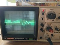
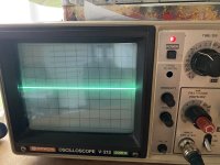
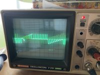
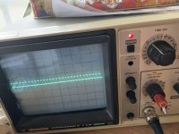
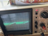
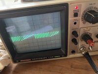
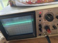
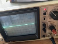
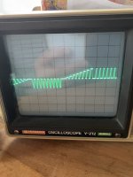
I would be expecting to see BOTH positive and negative pulses on both IC304 pin 2 and IC306 pin 2. These ICs operate as integrators, so the pulse should be present when you want the beam to move - and then not be present when you want it to be stationary. However, there may not be positive pulses depending upon how they are drawing the vectors... Can I just ask you to look (with different timebase settings) at IC304/2 and IC306/2 and see if there are any positive pulses or not?

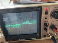
The other thing that is strange is the 'extra low' glitches that are appearing on IC306 pin 6 (and not on IC304 pin 6).

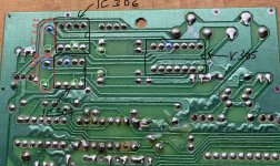
I would be suspecting a faulty IC305 (4066B) or IC306. It could also be the integrating capacitor associated with IC306.

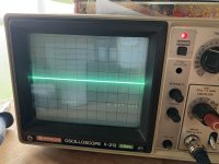
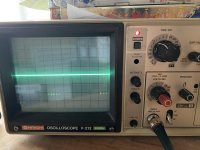
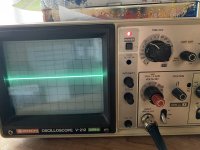
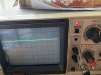
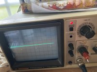
It might just be worth doing comparative checks with the oscilloscope as you move through the analogue circuitry between the X and Y channels and see what the differences are.

We do seem to be working in the dark (no pun intended - well, ok, a small pun intended). Should we also have a look at the Z signal path on the power board?

Dave
 
I was also surprised about the glitches at IC306-6 and I also found them at J301/X (of course). Did not notice it 2 weeks ago when I looked to J301 the first time. Back then I used a different scope setting and may overseen it…

Which one is the integrating capacitor for IC306? Is this one of the orange capacitors next to it?
How about to socket IC304 and IC306 and swap them? Maybe we can see the fault moving to the other axis?

About the comparative checks. What pins you suggest to scope?
 
>>> How about to socket IC304 and IC306 and swap them? Maybe we can see the fault moving to the other axis?

That is probably a good idea.

Yes, it may be one of the orange capacitors. The capacitor should be wired between the output of the OPAMP (pin 6) and the '-' input (pin 2).

I am a bit concerned about specifying actual IC and pin references as we don't have the correct schematic to work from. Perhaps the first order of the day is to find it? It must exist somewhere...

Dave
 
Good morning. I already searched a few times with Google but could not find it yet. Will try again.
Found the right capacitor. C312 connects between IC304-2 and IC304-6 as you said.
By the way C313 connects between IC306-2 and IC305-10. Thats different…

Thank you very much, Dave! Got a lot of things to do now 😊 Will take a while until I can reply results I guess….
 

Attachments

  • 1B71CA11-8CA8-40F6-9B8E-FC25499D8BD3.jpeg
    1B71CA11-8CA8-40F6-9B8E-FC25499D8BD3.jpeg
    1.2 MB · Views: 6
Just wanted to give a little update here.

I took the board out again and added the sockets for IC304, IC305 and IC306 plus one socket for the Audio AMP chip LM386. I can confirm that no harm happened to the board :) . Checked the R326 Pot (incorporated in the Power Switch). Identified Input, Output and connection to digital ground. Connectivity looks all good. Can also measure with the multimeter that the resistance goes smoothly up and down (0-10 kOhm) when turning the switch. Good.

Without correct schematic (still not found for the low buzz 3GE model) I am struggling to check the traces from and to the LM386. But one thing I found very strange. The ground connection of the R326 does not connect to ground but to -5VDC. This could not be right? I have just double checked whether there is a short between -5VDC and GND. Its not.

Very confusing without schematic. I will keep searching for it ...
 
Last edited:
How do we identify a 'low buzz' 3GE from a normal 3GE?
I have a 3GE but it does buzz, I just don't have anything to compare it to, so I don't know whether it's 'low buzz' or not.
 
It is in the analogue section of the Vectrex logic board - with the OPAMPS.

One has MC34001P devices. However, the older type OPAMPs may also have been replaced...

Dave
 
A easy way is to look at the row of caps on bottom board (logic board). The Buzzing version has three caps in a neat row to the left (seen from the back of the vectrex) while the no-buzz only have two, difrent size, caps there. Theres also two small caps next to the speaker conector between the controller ports.
 
Back
Top