• Please review our updated Terms and Rules here

Vectrex Repair (another no buzz 3GE version)

Good morning. looks like you did a Night Shift. Thats sad that replacing IC401 did not solve your problem and you probably feel frustrated now. Happened to me many times too. But still worth trying to adjust your vectors again. You replaced a chip related to that and according to my experiences the vectors might be off after changing a part.

If you are still in trouble….

Now as you replaced all ICs (did you?) maybe it’s good to step back and start from the beginning again. What always helped me is the troubleshooting guide. I found it here:. https://www.playvectrex.com/shoptalk_f.htm

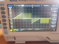
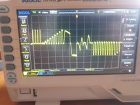
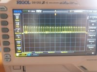
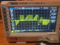
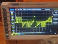
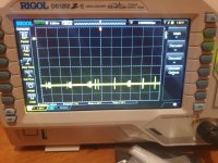
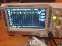
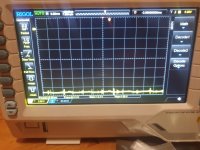
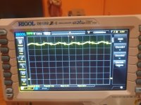
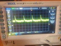
I would follow that guide and scope again all various pins related to the vectors. I know you have done it before but as your vectors are must misaligned you may need to look for the little details. Start with the x,y,z at the digital board (J402). And then follow the wires and scope again at their landing points at the analog board. Do the waveforms look exactly the same? Then follow the traces. You may want to start following up the x signal. Up to IC401. Look for small differences. Maybe you will find a spot when the waveform starts to look weird. You can refer to my screen shots I have posted on the other thread.

i am not sure but maybe you are dealing with a marginal working item or a bad contact or a short somewhere? Only with your scope you will find it.

good luck!
 
Hi at all, today i have a time to make photo of signals, i starts from logic board at XYZ connector from it to analog.

Starting from schematics pin 1 is not connected, 2 is Y axis, 3 is X axis and 4 is Z axis.

Respective i attached the photos and a little video on the Z axis because i don't know if is normal the peak it have during probe.

The scope is setted with probe at x1 and 1.00ms time div and 10.0v/div

photo 105954 and video 110017 is Z axis
photo 105917 is the pin 2 Y axis
photo 105940 is the pin 3 X axis

Based from troubleshoting guide the X axis signal is wrong, right?
 

Attachments

  • 20231115_105917.jpg
    20231115_105917.jpg
    2 MB · Views: 3
  • 20231115_105940.jpg
    20231115_105940.jpg
    1.8 MB · Views: 3
  • 20231115_105954.jpg
    20231115_105954.jpg
    1.9 MB · Views: 3
  • 20231115_110017.mp4
    3.8 MB
Can you follow the signal back (indicated in photograph 105940) with your oscilloscope - following the schematic and the PCB tracks.

Dave
 
Yes, now i have a medical visit, when return to home i check backward, on logic board right?
 
Last edited:
X looks really weird. Fully agree. The problem is obviously on the logic board.
Can you please also scope pin 10 at IC305 and pin 14 at IC 303?
 
The signals on pin 10 of ic 305 and pin 14 of ic303 are the same.

I have reinstalled all original vector and dac chip, and cpu, not the lm379 and not the 6522 faulty. But same issue.

Note: if i remove the 4066 and turn on the system the Z axis don't have the peak in previous attached video, is the same of troubleshoting signals page and costant.

photo 165055 is x axis
photo 165122 is y axis

i have probed same signals at 4066 pin 10 for x axis and 4066 pin 2 for y axis.

I have also tested six 4066 different chip.
 

Attachments

  • 20231115_165055.jpg
    20231115_165055.jpg
    2.5 MB · Views: 0
  • 20231115_165122.jpg
    20231115_165122.jpg
    2.6 MB · Views: 0
Last edited:
That is very interesting!

The 4066 has nothing to do with the Z axis...

So either there is a strange 'sneak path' somewhere (a short circuit for example), or something is affecting the +5V ANA and/or the -5V ANA supply rails.

I would just double-check the analogue supply rails first (with the 4066 in) to make sure they are not fluctuating.

Dave
 
It doesn't matter where you measure the + and - 5V ANA signals. They don't have to be on the 4066.

From my notes, 4066 pins 7 and 14.

Measure relative to 0V/GND.

Dave
 
This is probe with scope on pin 14 (+5v ANA) and pin 7 (-5v ANA) on 4066, same at pin 16 and 7 on 4052-

photo 172056 is +5v ana (with multimeter is 4,88volt)
photo 172134 is -5v ana (with multimeter is -4,94volt)

probe settings are x10 and scope v/div=1volt and time/div 5.00ms

In effect is not a pure line... the scope report v peak max 5,6vpp and -4,28vpp !!
 

Attachments

  • 20231115_172134.jpg
    20231115_172134.jpg
    2.1 MB · Views: 2
  • 20231115_172056.jpg
    20231115_172056.jpg
    814.4 KB · Views: 2
Last edited:
I have also measured voltage on tube nek board, i have 171v on 170v rail, 49.8 on 50v rail, and 7v.

At the moment the system have same issue when hot or cold, but now the grid of test cart don't going to a good condition, it remain little distorted and the two regolation trimmers change any vector but not perfect allineed!
 
Last edited:
I have checked also power line on analog at this point T401 (my analog don't have this T401 but only two inductor, schematics reports -9v and + 9v but i have -12v and 12v, with scope the two signals are in attached photo.


1700069255631.png
 

Attachments

  • 20231115_182818.jpg
    20231115_182818.jpg
    1.9 MB · Views: 1
  • 20231115_182852.jpg
    20231115_182852.jpg
    2 MB · Views: 1
So it is highly unlikely to be power rail related then.

The +/- 9V supplies are all unregulated. So the stated value is somewhat questionable in the first place.

Dave
 
Check IC303 pins 10 and 8 with the 4066 both IN and OUT, looking for differences.

My IC reference is the older Vectrex board of course. These are the Z axis output from the 4052 multiplexer and the output from the Z axis sample and hold operational amplifier.

We need to look for differences that occur with the 4066 in and out, working our way back to the earliest part of the analogue circuitry on the logic board.

Dave
 
Ok dave, in base of this schematics, similar to my no buz board but not same, the pin 15 of 4052 going to MC34004 pin 5, the signals is on photo, then the output of this op, from datasheet, is the pin 7, it's going to 1n4148 diode and then to Z axis wire connector.

In this post i attach the signals from 4052 and output from pin 7 of MC34004:

photo 185826 are pin 15 of 4052, then photo 185857 is output of op pin 7 to diode D302 and then to z axis connector.

Now i have to check al pins of 4066?
1700072021631.png
 

Attachments

  • 20231115_185826.jpg
    20231115_185826.jpg
    1.9 MB · Views: 4
  • 20231115_185857.jpg
    20231115_185857.jpg
    2 MB · Views: 4
I think we have a language misunderstanding somewhere.

Are the two points above measured with the 4066 plugged in or not?

Dave
 
Ouch sorry, i don't understand last post, the measurement is with 4066 in.

Now is time to eat, then a measure without 4066.

Sorry
 
For complete, last measurement, schematics report pin 9 input connected to pin 8 output of op amp LF347, in my case is pin 6 connected to pin 7 and signals are the same on pin 6 and 7 (on MC34004)
 
Back
Top