• Please review our updated Terms and Rules here

Wang Series 700B Advanced Programming Calculator Refurb.

Usually, a scope probe has it's own "ground", or perhaps better called the signal return. That does not mean it literally should be connected to ground, but rather that it needs to anchored to the "other side" of the circuit. That would be MHG in this case, which is the "common" connection for both MHO and WDT.
Oh, I was looking for what MHG would be in all the wrong places. I wasn't sure if connecting the groundlead of the probe to the otherside of the resistor was a good idea.

When I was working on getting the expansion pcb for the Sharp PC7100 I was indeed able to filter out most noise to get a measurment on the clock (which is a much higher frequency that this). So it can get fairly clean measurements.
 
Ah, that looks a whole lot better.
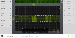
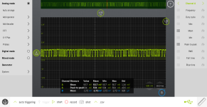
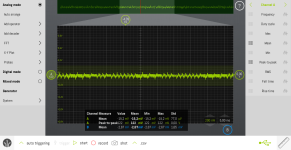
LabNation_Screenshot39.pngLabNation_Screenshot40.png

Also, the write protect system works. I was testing it with no tape in the drive and the tape ready pushed down and was not getting anything because the write protect switch was pushed.
 
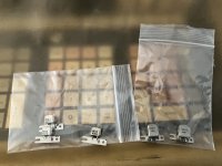
I got some new tapeheads in the mail today.

Tapeheads.jpg

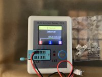
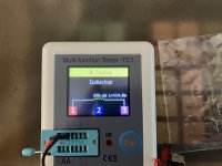
The set of 2 has a resistance of about 120 Ohms (according to the data on the ebaylisting). Measuring it with a cheap component tester gives it about 139 (close enough, this tester is not that accurate anyway).

Head1.jpg

The set of 3 is much more interesting, there was no real data on these from the seller. But measuring them gave 298 Ohms. The best guess for the original head so far is 270 Ohms, so close enough i guess. The testing earlier was done with a 220 Ohm resistor.

Head2.jpg

Not sure how the dimensions compare to the original one. the 120 Ohms seems a little larger. The other seems a smaller. The bracket style is the same though, might need some fiddling to get the allignment correct.
 
Last edited:
A quick and dirty alignment method: use a commercially recorded audio or data tape, and align for maximum signal.
Also check the head's guide is the same height on the fixed pillar as the origional was.
 
A quick and dirty alignment method: use a commercially recorded audio or data tape, and align for maximum signal.
Also check the head's guide is the same height on the fixed pillar as the origional was.
I have a bunch of tapes that came with the machine. I think it's just the dimensions of the head itself that are different, the position on the bracket would put the new head at about the same place as the old one.

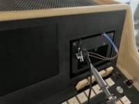
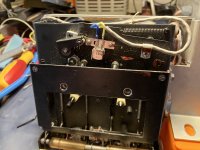
As for the time being i've zip-tied one of the 290 ohm heads to the cassette door for testing, just to see what kind of measurements I get out of it.
newhead-testing.jpg

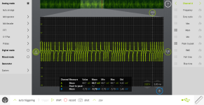
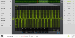
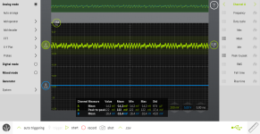
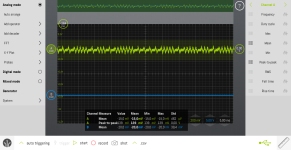
And I'm a little confused, I expected the scope readings to look different to the measurements with a resistor. But the peak to peak then was around 0,5 Volts (with a 220 Ohm resistor). Now, with the 290 Ohm head, the peak to peak is 10-11 Volts, but only for very small spikes. I guess that is the magnetic field in the coil collapsing or something like that? Or maybe better descriped as the signal being blocked by the coil at first increasing the voltage that way (I should probably say the changing of the signal)? The signal that could be seen in the previous shots is still there, altough now even smaller at around 0,3 Volts.
Again, a change in the reading was expected, just not sure if this is the correct change to expect.

LabNation_Screenshot42.png

LabNation_Screenshot43.png
 
Interesting, having never worked this closely with mag tape equipment, I'm not sure what to expect. I would have thought you'd still see the square-wave signal. Perhaps that is just the inductance. That does look more like what I'd expect when reading tapes. The spikes should represent the flux changes on the tape, and it looks like maybe the negative spike indicates the rising edge of the square-wave and the positive spike indicates the falling edge. Of course, spike polarity depends on how the scope leads are attached in relation to the record circuitry.
 
Interesting, having never worked this closely with mag tape equipment, I'm not sure what to expect. I would have thought you'd still see the square-wave signal. Perhaps that is just the inductance. That does look more like what I'd expect when reading tapes. The spikes should represent the flux changes on the tape, and it looks like maybe the negative spike indicates the rising edge of the square-wave and the positive spike indicates the falling edge. Of course, spike polarity depends on how the scope leads are attached in relation to the record circuitry.
I've been thinking about this and it makes sense to a degree to me. If I understand inductors correctly they resist the change in the polarity of the magnetic field that gets stored in them (inductors are not my strong suit when it comes to electronics). So I guess that spikes the voltage initially. I can see how this would transfer to tape in the way you described earlier.

I can also see how this might look more like a read signal then a write signal.
 
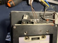
While mounting the new head I was able to take a good close up look at the old one. It seems to be either damaged or worn out. Under magnification it almost seems like there is a tiny crack down the middle of the silver square in the middle of the black bit of the head.

The new one fits pretty well, the mounting holes are a little to tight for the original screws but a small round file can't fix. The positioning of the head elements seems to work out quite well compared to the original one. I used some calipers to get a somewhat accurate reading to set the new one in more or less the same place as the old one. Just need to adjust the wire a bit to make them fit nicely in the drive.

Newhead.jpg

EDIT:

New shorter wires look better and would fit better too in the machine.

Newheadwired.jpg
 
Last edited:
From what little I remember about magnetic tape (and diskettes), one of the critical alignments is that the head is mounted exactly 90 degrees to the tape travel. The other, in order to read existing media, is that the tape head is aligned with the standard location of the track(s) on tape. As previously suggested, using a pre-recorded tape could be used, although I'm not sure if you'll get good results from audio tapes. From what I recall watching this procedure on floppy drives, you would adjust the location/tilt of the head and find the position with the strongest signal.

One worry about existing tapes is what might have happened to the recordings over the decades. I remember digging out some audio tapes after 20+ years and finding that the tracks had apparently "drifted" on the tape and you got garbled or even backwards playback (if a track had drifted into the other side). Hopefully that is not the case with these tapes.
 
The "crack" is the gap in the head which should be there and normally is filled with the epoxy the rest of the head is in. The head is formed in a U shape, with the open end facing the tape.

In VCR's Dat drives, the head gap is usually open, and can get clogged with residue from the tape and cause a magnetic "short", affecting performance. Not normally a problem on audio heads, where the gap isn't open.
Ah, I was hoping to find the actual failure point of the head. It has some obvious signs of wear aswell which is why I though the crack might be damage.

As I said before, I got a bunch of tapes with the machine and testing some in a normal cassette deck there is clearly something on the tapes. A high pitch noise with some low rumble and clicks hidden in it.

I tried one of the tapes that I tested in the normal deck and this is what came out of it:

LabNation_Screenshot44.png

LabNation_Screenshot45.png

It does somewhat look like the signal that comes out of the machine while writing. The highest signal strength I managed is around 140 to 150 mV (second shot).
 
Yes, that does look like something related to the expected pattern for Wang 700 tape data. Since that data contains parity, you should have some confidence if it loads without throwing a MACH ERR.
 
Oh wow... it's working!

I just recorded 200 program steppes of 07 00 (number 0) and an 05 12 (end program) to tape and then changed the the first few steps to 07 01 (number 1) and reloaded what I had written to tape. Not only does the tape now auto stop when done loading (this tape is otherwise blank). The changed position were set to 07 00 again.
 
Yes, that does look like something related to the expected pattern for Wang 700 tape data. Since that data contains parity, you should have some confidence if it loads without throwing a MACH ERR.
Yeah, no errors or anything. I haven't tried the stuff that is on the other tapes, but the saving and loading seems to be working.
Thanks you so much @durgadas311 for guiding me through this. And thank you @mark0x01 for the insights into tape stuff.
 
Doing some testing on using the cassette tape adapter to save and load data from and to the 700B. First, I used my scope to see what signal comes out of the tape adapter.

LabNation_Screenshot46.png
The signal is there, but it's very small. For me, this might be better as my bench mounted laptop only has a microphone input and I don't really now how much signal that input can handle.

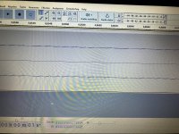
The fact that anything came through was interesting enough, so I installed Audacity onto the laptop and had it record the 200 steps of "07 00". I had to put the recording levels on max... but this is what I got.

Audacity.jpg

First off, the signal is the bottom track (I have to put the recording on mono, but this was just a quick test). I've become quite trained to the number 0 in Wang code (07 00) and can clearly see the combination in the recording. Not sure if this is enough of a signal to read back into the machine. I guess I should make a mono recording first to limit the noise being played from the stereo head otherwise.

It's promising though, as this could mean I can load the tapes I got with the machine into memory and then make backups of whatever is on them.
 
Yeah, the sensitivity and impedance (and gain) of the Wang playback circuitry is probably nothing like audio counterparts, let alone modern ones. One can certainly see the data in the signal, though.
 
Wang seemed to be attached to using these Philips cassettes for far too long. There's even a model of the 2200 ("G") that used them, as well as some of the early WP gear. Jim Battle has a github project where he uses a stereo tape deck to read them.
 
Yeah, the sensitivity and impedance (and gain) of the Wang playback circuitry is probably nothing like audio counterparts, let alone modern ones. One can certainly see the data in the signal, though.
Reading it back into the machine seems a bit to much to ask on a quick little testrun... It's reading something back, and it seems to get some of the data in correctly, but it's very hit and miss. Up the volume 1%, machine error. Down 1% percent, nothing... it doesn't get anything at all. And if you find some sweet spot where the stars seem to align it garbles some parts but gets others correctly (and these are 200 "0"'s, so they should all be the same).

Wang seemed to be attached to using these Philips cassettes for far too long. There's even a model of the 2200 ("G") that used them, as well as some of the early WP gear. Jim Battle has a github project where he uses a stereo tape deck to read them.
That was one of my ideas as well, but all of the tapedecks I own had gooy belts. I got one to the point where it plays again but it's not a good belt and rest of the mechanism is only more or less working. It was just good enough to prove data was on a tape.

I will have to open the machine over the weekend and scope the head to see what quality of signal comes out the the cassette adapter, as that might be terrible.
 
Back
Top